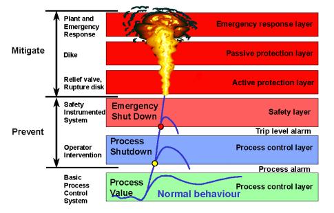
Safety in a plant is provided by layers of protection. The diagram from Emerson SIS Course[1] shows the Safety Instrumented System (SIS) as the “safety layer” providing the final preventive layer before the mitigation layers must engage.
Typically, safety instrumented systems (commonly known as Emergency Shutdown (ESD), Emergency Venting (ESV) or Safety Interlock Systems) consist of the three elements of Figure 2:
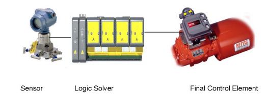
The SIS must be completely independent of the process control system. Its sensors are dedicated to SIS service and have process taps which are separate and distinct from the process taps used by normal process control information sensors. Highly reliable logic solvers execute programmed actions in response to sensor signals to prevent a hazard. The logic solvers must provide both fail-safe and fault-tolerant operation.
IEC Standard 61508 (Functional Safety of Electric, Electronic and Programmable Electronic Systems) is a general standard that covers functional safety related to all kinds of processing and manufacturing plants. IEC Standard 61511 and ISA S84.01 (Replaced by ISA 84.00.01-2004) are standards specific to the process industries. These standards specify precise levels of safety and quantifiable proof of compliance.
IEC standards specify four possible Safety Integrity Levels (SIL1, SIL2, SIL3, SIL4); however, ISA S84.01 only recognizes up to SIL3 levels.
| SAFETY INTEGRITY LEVEL (SIL) | REQUIRED SAFETY AVAILABILITY (RSA) | AVERAGE PROBABILITY OF FAILURE ON DEMAND (PFD) =1-RSA |
| 1 | 90 −99% | 0.1 to 0.01 |
| 2 | 99 −99.9% | 0.01 to 0.001 |
| 3 | 99.9 −99.99% | 0.001 to 0.0001 |
| 4 | 99.99% −99.999% | 0.0001 to 0.00001 |
The Probability of Failure on Demand (PFD) is value that indicates the probability of a system failing to respond to a demand. The average probability of a system failing to respond to a demand in a specified time interval is referred as PFDavg. PFD equals 1 minus Safety Availability.
Risk is composed of probability (frequency of occurrence) and consequences (severity). The probability component of risk:
| RISK LEVEL | DESCRIPTIVE WORD | FREQUENCY OF OCCURRENCE |
| 5 | Frequent | One per year |
| 4 | Probable | One per 10 years |
| 3 | Occasional | One per 100 years |
| 2 | Remote | One per 1,000 years |
| 1 | Improbable | One per 10,000 years |
The severity component:
| RISK LEVEL | DESCRIPTIVE WORD | POTENTIAL CONSEQUENCES TO PERSONNEL |
| 5 | Catastrophic | Multiple deaths |
| 4 | Severe | Death |
| 3 | Serious | Lost time accident |
| 2 | Minor | Medical treatment |
| 1 | Negligible | No injury |
The total overall risk can be determined by multiplying the Risk Level factors from the two tables to obtain a number from 1 to 25. If this product falls between 15 and 25, the risk is considered high and would indicate a possible need for a SIL3. For a product between 6 and 15, the risk is considered moderate and a SIL2 may be called for. If the product falls between 1 and 6, the risk is considered low and a SIL1 may be adequate.
An analysis needs to be performed for each hazardous event for each safety function. Once this is done, the analyst needs to consider the level of protection that may be provided by other Independent Protection Layers (IPLs) such as; basic process control functions, alarms and operator intervention, physical protection such as relief devices or dikes, plant emergency response measures, community emergency measures, etc referred to in Figure 1. Taking all of these factors into consideration, the analyst then can assign an overall SIL target level to each SIS system. The designer then must design the SIS system equipment to possess probability of failure on demand (PFD) characteristics that will meet that Safety Integrity Level.
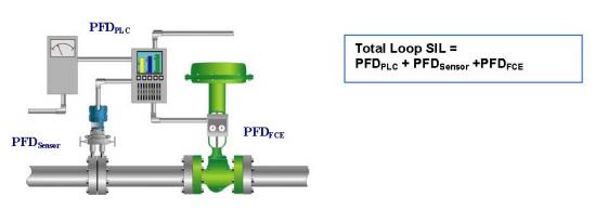
The PFD for the SIS system is the sum of PFDs for each element of the system (Figure 3). In order to determine the PFD of each element, the analyst needs documented, historical failure rate data for each element. This failure rate (dangerous[2]) is used in conjunction with the Test Interval (TI)[3] term to calculate the PFD. It is this test interval (TI) that accounts for the length of time before a covert fault is discovered through testing. Increases in the test interval directly impact the PFD value in a linear manner; i.e., if you double the interval between tests, you will double the Probability for Failure on Demand, and make it twice as difficult to meet the target SIL. The governing standards for Safety Instrumented Systems state that plant operators must determine and document that equipment is designed, maintained, inspected, tested, and operated in a safe manner. Thus, it is imperative that these components of Safety Instrumented System be tested frequently enough to reduce the PFD and meet the target SIL.
Final Control Elements represent a significant failure contribution in an SIS loop. If offline testing is not possible, then how do we test dormant valves that remain in one position (by nature of the application) without any mechanical movement?
Conventional methods and problems:
| Test Strategy | Drawbacks |
| Install a bypass valve around each safety valve. By placing the bypass in service, the safety valve can be full−stroke tested without shutting down the process. |
|
| Mechanical limiting travel methods by use of a mechanical device, such as a pin, a valve stem collar, a valve hand jack, etc. that will limit the valve travel to 15% or less of the valve stroke |
|
Problem:
Safety Instrumented Systems (SIS) are required by standards IEC61508/ISA S84.01 (Replaced by ISA 84.00.01−2004) to be tested at a periodic interval based on HAZOP (Hazard Operation Analysis) design to achieve and meet a required Safety Integrity Level (SIL). However, pressure to maximize production are forcing process industries to extend shutdown intervals to 3, or in some cases, 5 years. Final Control Elements consisting of dormant valves that remain in one position without any mechanical movement remain untested for a longer time than required to achieve SIL. Workarounds such as mechanical valve limiters, and bypass piping have two disadvantages: One, that the the SIS is unavailable during the test period, and two, that the limiting or bypass valve can be left inadvertently in test mode.
Solution – Digital Valve Controller:
Using digital valve controllers on Safety Shutdown valves to detect dangerous failures provides for local and remote testing while the plant is running. Not only is testing performed at the required TI but the test data revealing valve condition is documented and stored automatically thereby adding a CBM layer to the SIS that identifies partially failing valves. Should an emergency shutdown demand occur during testing, the digital valve controller will override the test, driving the valve to its safe position.
The SIS has the capability to alert the operator if, during a test, a valve is stuck. As the positioner begins the partial stroke, it continually checks the valve travel to see if it is responding properly. This is important to reduce false trips. Conventional positioners, which do not see travel feedback, may exhaust actuator pressure trying to move a sticking valve. If the spring force frees the stuck valve after air is depleted, a false trip could
occur. However, the digital valve controller has configurable minimum partial stroke air pressure in microprocessor memory. Should the valve be in the stuck position, the digital valve controller will abort the test before pressure drops enough to cause a false trip, and alert the operator that the valve is stuck. This will prevent the valve from slamming
shut if the valve does eventually break loose.
Digital valve controllers (aka “smart” positioners) are communicating, microprocessor-based current-to-pneumatic instruments with internal logic capability. In addition to the traditional function of converting a current signal to a pressure signal to operate the valve, these digital valve controllers use HART[4] communications protocol to give easy access to information critical to safety testing.
The digital valve controller receives feedback of the valve travel position plus supply and actuator pneumatic pressures. This allows the digital valve controller to diagnose the health and operation of itself and the valve and actuator to which it is mounted.
The operator initiates testing by a simple button push, however the testing sequence itself is completely automatic, thereby eliminating any errors and possible nuisance trips, and the labor capital cost of conventional testing schemes.
Typically the partial-stroke test moves the valve 10% from its original position but can be up to 30% if allowed by plant safety guidelines. Partial-stroke testing does not eliminate the need for full-stroke testing. Full-stroke testing is required to check valve seating, etc. Nevertheless, partial stroke testing does reduce the required full-stroke testing frequency to the point where it can most likely be tested during the scheduled plant turnaround.
Because the positioner communicates via a bus HART protocol, the partial stroke test can be initiated from a hand-held communicator, from the control panel, or from a panel-mounted push button hardwired to the positioner terminals. The operator can also schedule tests automatically on a daily, weekly or monthly basis.
A final consideration – Verifying the TI via LRCM
The discovery of a failed safety device is a valuable, yet largely ignored “data point” in a Reliability Analysis (RA) sample. Such data points constituting a sample should be analyzed in order to determine whether the testing frequency is adequate by calculating the real reliability (MTBF) of the device, which could differ substantially in the actual operating context from the manufacturers published data. Whenever a test is performed manually by the operator and a malfunction is reported, the resulting EAM work order should record the failure mode’s ending Event Type as a “Potential Failure”.[5] Why would we call the functional failure of a safety device a potential failure? It is because the multiple failure, in other words the the device being in a failed state at a moment when it is needed, has been prevented.
- [1]http://www.documentation.emersonprocess.com/groups/public_valvesprodlit/documents/training_info/sis_training_course_1.pdf↩
- [2]excluding the nuisance failures↩
- [3]Failure Finding Interval in RCM terminology.↩
- [4]Highway Addressable Remote Transducer Protocol is an implementation of Fieldbus, a digital industrial automation protocol. It can communicate over legacy 4-20 mA analog instrumentation wiring, sharing the pair of wires used by an older system. The huge installed base of 4-20 mA systems throughout the world makes the HART Protocol is one of the most popular industrial protocols today.↩
- [5]During scheduled shutdowns, if the device is replaced or renewed proactively, that action should be recorded as a suspension.↩