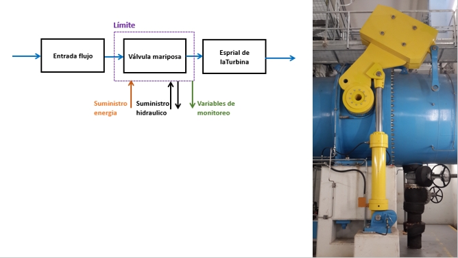
In performing your RCM analysis on this butterfly valve, you decided to treat the hydraulic system as a separate analysis. You drew the boundary in such a way that the cylinder-actuator belongs to the hydraulic system and not to the valve. That is perfectly legitimate. You can draw the boundaries in any way that you find convenient.
Now you ask whether you should list, or in some way, reference in the valve’s RCM analysis, a failure mode affecting the valve but occurring within the hydraulic system. If so, how should you include this reference?
Assume that the failure mode identified in the hydraulic system analysis is:
- Object part =”Cylinder”,
- Object damage = “Seal leaks”,
Should we list this failure mode in the Valve analysis as a general description, say
- Object part: “Hydraulic system”
- Object damage: “Fails”
Traditionally, in RCM analysis, this would not present any problem. You would simply indicate in the comment text area that the failure mode is analyzed elsewhere. You would not include a mitigating action within this appearance of the failure mode.
However LRCM works day-to-day with the RCM analysis where technicians select failure mode work order instances directly from the RCM tree. Furthermore, LRCM builds upon the RCM analysis as new information comes to light. If the failure mode is represented in two RCM locations, you have the possibility that some technicians will erroneously select the general failure mode leaf in the valve’s RCM tree. Other technicians will correctly select the specific failure mode in the hydraulic system’s RCM knowledge tree. This will result in separate instance counts of what really should be the same failure mode. The samples used by reliability analysis algorithms would be distorted. The reliability analyst would analyze two failure mode instance samples rather than one.
Here is a simple solution in Mesh, which is consistent with John Moubray’s RCM II approach regarding failure modes handled elsewhere. In the RCM valve analysis describe the failure mode as follows:
- Object part = Hydraulic System.
- Object damage = “Fails”,
- Due to = “See Hydraulic system analysis”.
In this way the technician will know, without needing to unfold the leaf, that he should not select this failure mode but rather he should locate the specific failure mode in the Hydraulic System’s RCM knowledge tree. [1]
A second related issue concerns the generation of the maintenance schedules. Since the RCM analysis is represented in a dashboard we need to avoid duplicate failure modes for two reasons. One, the count of failure modes would be distorted when filtering on one or both of the two systems involved. Secondly, the maintenance schedules would contain the failure mode in both its general and specific form. A simple solution would include the code “{gen}” in the Effects text (similarly to the method proposed in the article on common cause failures). The extraction, transformation, and loading (ETL) program will skip the general failure mode. thereby precluding its appearance in the RCM tasks dashboard and in the maintenance schedules.
This was an interesting situation that came to light because of the LRCM extension and its functionality requiring the RCM analysis to be integrated into the daily work order process.
## Post Tree Navigation
LRCM
- CMMS Impediments to Reliability Analysis
- Components of continuous improvement
- How to start LRCM
- Justifying Living RCM Certified
- Leading and lagging performance numbers
- Living RCM Certified – Consulting Services
- LRCM – Reporting failure modes of rotable components
- LRCM and HSE
- LRCM Justification Template
- LRCM reliability analyst survey results
- LRCM reliability technician survey results
- MESH – RCM knowledge continuous improvement
- Motivation, leadership, training
- PAS-55
- RCM – Dashboards
- Reliability engineer’s work cycle
- Service vs. maintenance
- Streamlined RCM and LRCM
- Structured free text
- The role of media in living RCM
- The winning paper at the XIV International Congress of Maintenance
- Two philosophies in maintenance improvement
- Waiting for CMMS maturity
- What is a pilot project?
- What is the difference between RCM and LRCM?
- Achieving Reliability from Data outline with video
- Course brochure – Living RCM Certified
- Deepwater Horizon
- Elevator description of LRCM
- How does LRCM “improve” RCM?
- Living RCM Certified
- Living RCM Certified eLearning
- Living RCM Certified® and ISO 14224
- LRCM – off the maintenance improvement radar
- LRCM-EXAKT – a general solution
- MESH Basic reliability analysis on the work order
- Mesh Living RCM Certified brochure – Mesh Cloud Service
- Obtener confiabilidad a partir de los datos – esquema del curso
- RCM – Analyst course outline
- RCM – feedback suggestion mechanism
- RCM – Living RCM
- RCM – LRCM dashboards
- RCM – feedback – suggesting a new failure mode
- Training course in achieving reliability from data
- Two kinds of decision making in maintenance
- Two LRCM purposes
- Videos
- Why Living RCM works
RCM
Reliability Analysis
- Achieving Reliability from Data
- Challenges to Achieving Reliability from Data
- Data analysis precedes reliability analysis
- Data is the key to the way forward
- Defeating CBM
- Does historical age data have value?
- Failure declaration standards
- Free text on the work order
- How much data is required for RA?
- How to assess EAM and CBM predictive capability
- Interpreting failure data
- LRCM – Reporting failure modes of rotable components
- Maintenance software
- Mesh: 12 steps to achieving reliability from data
- RA requires LRCM
- Reliability analysis in 2 dimensions-Part 2
- Sample selection
- So you’re getting an EAM
- Take the EAM data health check
- The CMMS barrier to RCM
- The data barrier to analysis
- The reliability data Catch 22
- Thoughts from a mine maintenance engineer
- Variations in a sample
- Warranty for haul trucks
- Weibull exercises
- What’s the right data?
- A survey of signal processing and decision technologies for CBM
- Achieving reliability from data
- CBM Defined
- Conditional failure probability, reliability, and failure rate
- Conditional probability of failure
- Conditional probability of failure vs. hazard rate
- Criticality analysis in RCM
- Diagnostics versus prognostics
- Difference between LRCM and EXAKT
- EXAKT’s Three Modules
- Expected failure time for an item whose maintenance policy is time-based
- Failure analysis for reliability analysis
- Failure probability prior to attaining MTTF
- FAQ
- FMEA according to Wikipedia
- Is “random failure” really random?
- Leading and lagging performance numbers
- LRCM and the Failure Finding Interval
- MTTF is the area under the reliability curve
- Myths about RCM in heavy mining equipment
- Non-rejuvenating events
- Optimal PM and spares strategies – exercises
- Performance metrics – Low and High level KPIs
- Problem statement
- Purpose of RA
- RA – Micro (day-to-day decision) analysis
- Random failure and the MTTF
- Random failure is exponential reliability decay
- RCM – Living RCM: Achieving reliability from data
- RCM vs RA
- Real meaning of the six RCM curves
- Reliability analysis is counting
- Reliability trend yes Weibull analysis no
- Remaining Useful Life Estimation Using Hybrid Monte-Carlo Simulation and Proportional Hazard Model
- Safety Instrumented Systems
- TBM or CBM?
- Terminology in LRCM
- Thinking RCM
- Time to failure
- What is PM?
- What is the scale parameter?
CBM
- A survey of signal processing and decision technologies for CBM
- Automating CBM
- Building a CBM decision model
- CBM Exercises
- CBM Optimization
- Combined analysis for early predictive maintenance
- Deploying the CBM model
- EXAKT cost sensitivity analysis
- EXAKT needs LRCM
- EXAKT vs Weibull
- Measuring and Improving CBM Effectiveness
- Optimizing a Condition Based Maintenance Program with Gearbox Tooth Failure
- RCM – Reliability analysis in more than two dimensions is CBM
- Smart CBM demo
- What is Maintenance Decision Automation?
- Confidence in predictive maintenance
- Diagnostics versus prognostics
- Inspections – CBM and others
- Inspections or CBM?
- Internal and external CBM variables
- NAVAIR and the PF interval
- Objectivity in condition based maintenance decisions
- Optimized interpretation of CBM data
- P-F Interval a red herring?
- PF interval from the failure rate
- PM, PdM, Proactive Maintenance
- Predictive analytics
- Temporary fix work orders
- The elusive P-F interval
- [1]As a road map item, we can disallow certain general failure modes from being selected if they are fully analyzed elsewhere.↩
- How much detail? (50.2%)
- Conditional probability of failure vs. hazard rate (46%)
- Effects (34.5%)
- Local, Next higher level, End effects (34.5%)
- Criticality analysis in RCM (34.5%)
- Structured free text (RANDOM – 4.2%)