Glossary
Tree, hierarchy, knowledge base: The expandable list representing an Equipment type or Fleet and its Systems, Subsystems, Components, Functions, Failures, and Failure Modes. The elements: Components, Subsystems, or Systems elements may be excluded from any branch of the tree.
Equipment, fleet: The highest element in a heirarchy. Represents a type of equipment. For example Hitachi Electric Truck 320T.
Knowledge element, element: A node on the tree representing one of: Equipment, System, Subsystem, Component, or Failure mode.
Consequences: The reason why the failure matters. The choices are:
- Hidden
- Safety, Health, Environmental
- Operational
- Non-operational
Mitigation Task: An activity that must be done pro-actively to avoid or reduce the consequences of faillure. The choices are:
- Time (age) based maintenance.
- Condition based maintenance.
- No maintenance, allow function to fail and then repair
- Inspection (Failure Finding) to see if a function has failed.
- Redesign – a one time change in the asset, its operation or manitenance procedures, or associated training.
Corrective Task: A reactive activity that must be done following a failure.
Use Cases for MESH Knowledge Builder
Objective: Create and update the RCM knowledge base using MESH Knowledge Builder
Actor(s): Reliability Analyst
Activities:
- Create a new fleet
- Edit fleet information
- Access the fleet hierarchy
- Add a knowledge element
- An element other than a failure mode
- A failure mode
- Modify a knowledge element
- An element other than a failure mode
- A failure mode
- Move an element up or down in the tree
- Copy an element and paste in another another location
- Delete an element
- View a Failure mode
| Activity 1. Create a new Fleet |
User Action: 1. Start MESH in web browser
System response: Knowledge Base – Fleet Administration main display
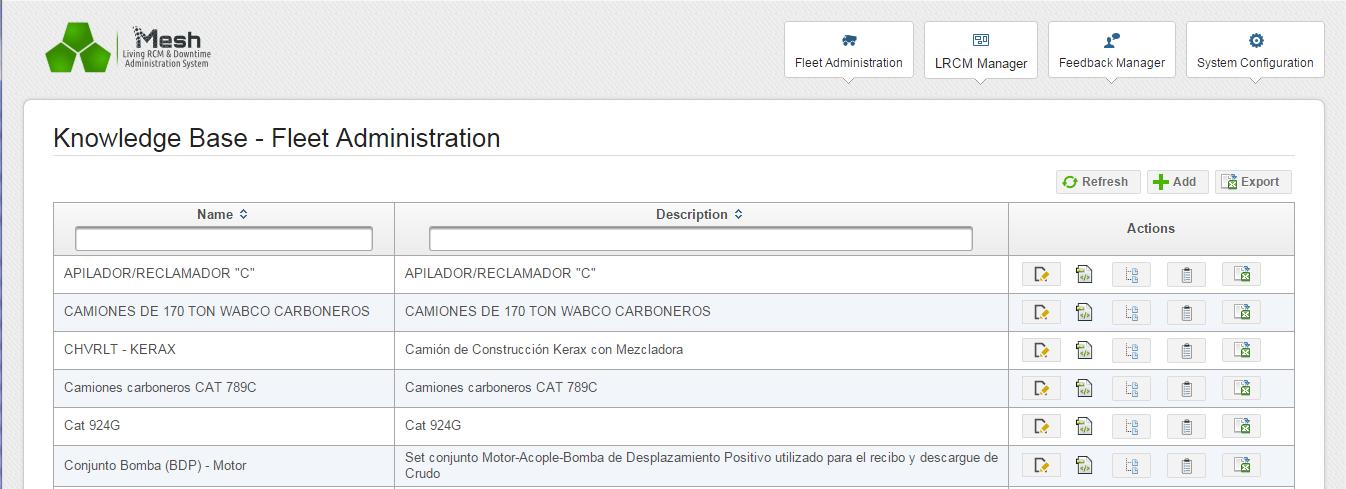
User Action: Hit the +Add button
![]()
System response: 2. Input fleet data dialog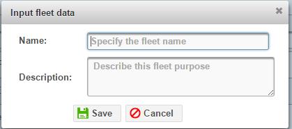
User Action: 3. Enter data, Save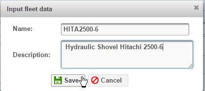
Activity succeeds: Dialog closes. List displays with new equipment added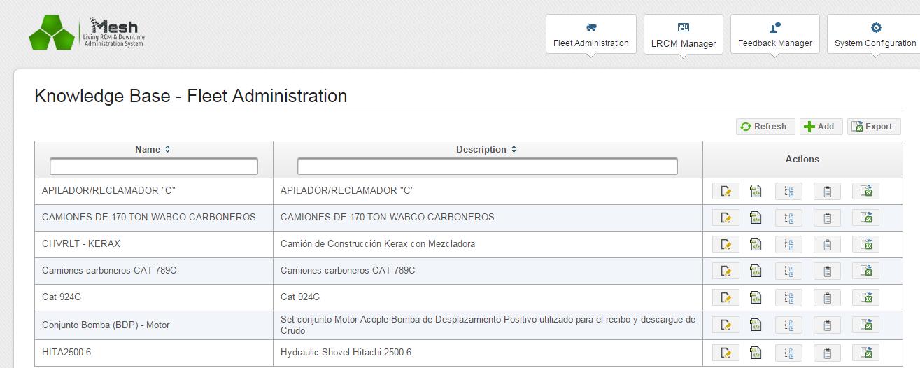
| Activity 2. Edit equipment information |
User Action: 2.1 Hit Edit fleet information icon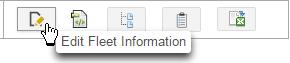 System response: Same dialog as Activity 1 User action 3
User Action: 2.2 Edit data. Save
Activity succeeds: Dialog closes
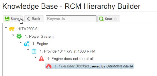
| Activity 3. Access the fleet knowledge base |
User Action: 3.1 Hit the Build Knowledge icon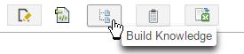 Activity succeeds: Tree view of knowledge base appears
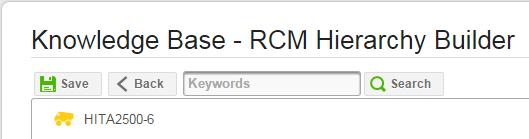
| Activity 4A. Add a new knowledge element (other than a failure mode) |
User Action: 4.1 Right click the element below which you wish to add a new element. Select Append. Select the Element type you wish to add.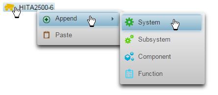
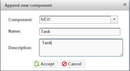
System response: Append new element dialog appears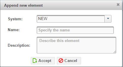
User Action: 4.2 Edit information. Hit Accept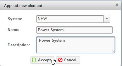 Activity succeeds: New element appears in tree view. Hit Save to accept
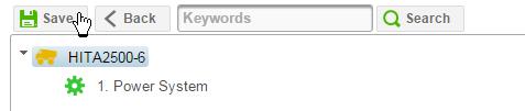
Repeat this activity to append additional elements to the equipment tree. For example add a Component, a Function, and a Functional Failure so that the tree view now looks similar to this: 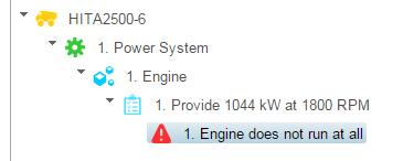
| Activity 4B. Add a failure mode |
User Action: 5.1 Right click a Functional failure and select Append and Failure Mode from the context menu.

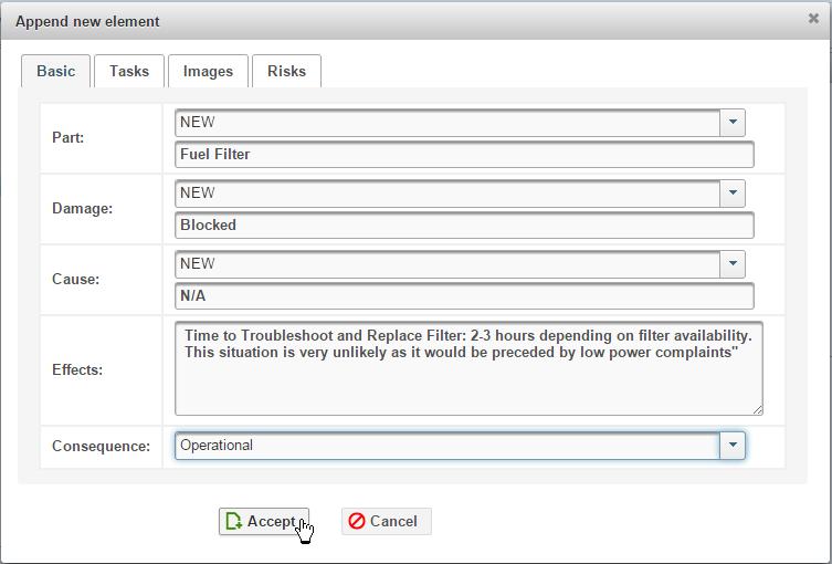
System response: The Append new element (Failure Mode) dialog displays: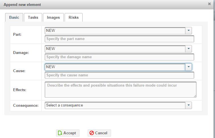
User Action: 5.2 Complete the Failure Mode (Basic) information as shown:
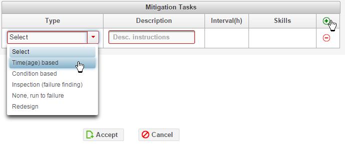
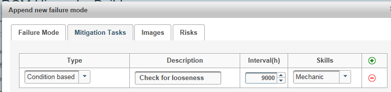
User Action: 5.3 Hit the Tasks tab, the add icon and select a mitigation task type.
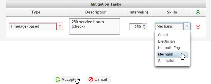
User Action: 5.4 Enter the Description, Interval, and select a Skill:
User Action: 5.5 Hit the Images tab and upload an image (if required) to illustrate the Failure Mode’s Failure, Potential Failure, or Suspension states.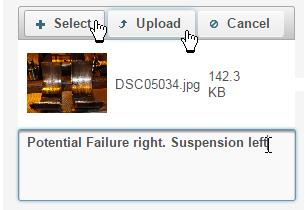
System response: System uploads and displays in the dialog the selected image file. 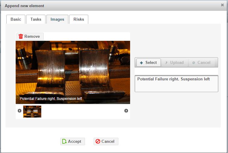
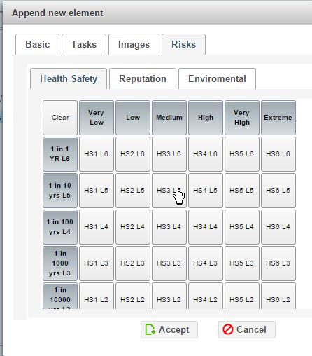
User Action: 5.6 Hit the Risks tab. And select a grid square corresponding to the probability and severity of the Failure mode.
User Action: 5.7 Select the Reputation, then the Environmental tabs making respective severity and probability selections. Hit Accept: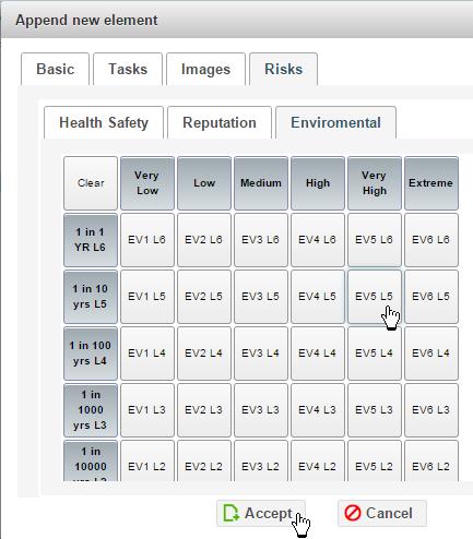
Activity succeeds: System closes dialog and displays tree view with new Failure Mode appended onto the tree.
| Activities 5 to 9. Modify, copy, and move elements. |
User Action: 1. Right click an element in the tree and select the desired context menu activity choice. 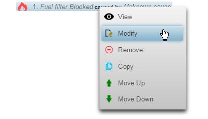
Follow similar procedures to those in Activities 1 to 4B above to complete the required action.
Activities succeed: Hit Save. The system displays success message. 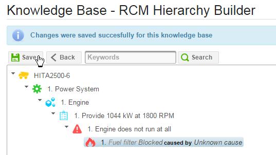
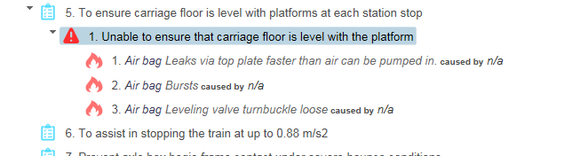
Note that in most cases a “debido a” is not relevant. From a purely esthetic reason, when n/a is given as the cause KB could avoid displaying the third grammatical element of the failure mode “caused by n/a”. This would look much better. This is more than just looks. There is an important RCM principle here. The principle is that the amount of depth in the causality chain is governed by the value of that information. If the information has no value it should not be recorded nor displayed as it introduces more clutter. The idea of RCM is to present the failure behavior of an asset as simply as possible.
The interval between repetitive mitigation tasks is not necessarily in hours. In this case it is km. Better to remove the (h).
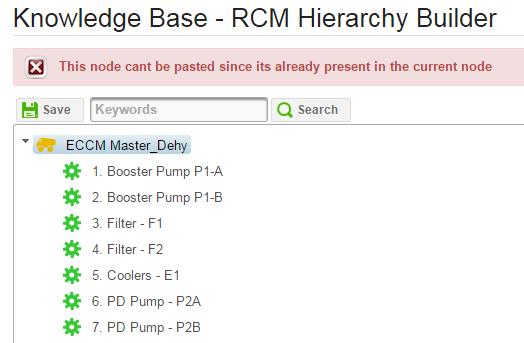
Copy-paste: Pasted item needs a page refresh to become visible.
Need 200 characters for Function Statement:
E.g. typical function statement: “To insulate passengers from shocks caused by crossing rail joints, bumps and to minimize transient oscillations after crossing such bumps.”
The description should be optional or it should default to the name. In 90% of the cases the Description does not add any more information. This would be the case for all knowledge elements.
There needs to be a “collapse all” button
It doesn’t seem right that changes made in KB are not immediately committed. If there is a power failure or someone accidentally closes the browser, work is lost. If saving in necessary I believe there should be an auto save every two minutes.
Building an initial knowledge base involves a lot of repetitive operations. When, for example, after appending a subnode in a node that is way down at the bottom of the tree the focus jumps to the top of the tree. Then the user as to scroll down and find the node that he was working on. Can we fix this by keeping the focus at the last place the user was working? This problem will be particularly annoying when working with Knowledge Builder in a group setting.
There is no reason to have a minimum number of characters in either field
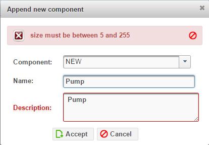
[8:01:24 AM] Fabio Turizo: Ok, for the minimum lenght of elements i’ve reduced it to 3
[8:01:55 AM] Murray Wiseman: Cool. Thanks.
It is often required to copy a subnode into the same node, and then edit the copy of the subnode. Tried to dublicate PDPump – P2B and change the duplicate to P2C Not allowed? When there is a conflict like this, the operation should be allowed by automatically creating a modified element, by appending say “_1”
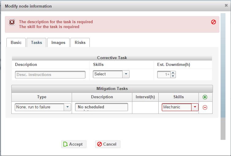
Two points regarding Corrective Task information in the image of the previous comment:
1. The Description free text field should be an expandable text area so that the user can conveniently see what he is writing.
2. The whole Corrective Task information block needs to be moved into the first tab as a sub section under Effects.
If None, Run to failure selected, description, interval, and skill should not be required.
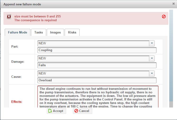
Effects appears to be limited to 255 characters. That’s not enough. The Efectos is the entire story of what happens when a failure mode occurs. This can include all kinds of technical and organizational details.
[12:38:15 PM | Edited 12:38:19 PM] Fabio Turizo: Mmm, okaay i’ll queue that change to the system, since i would have to consider some things regarding the layout and storage, but as you say it makes sense
[12:38:45 PM] Murray Wiseman: Thanks.